Would you like to make this site your homepage? It's fast and easy...
Yes, Please make this my home page!
The Clipper Air Brake System
A. Overview
Although the evolution of the Air Brake System for heavy vehicles
involved a number of "refinements" over the years, the Bendix system as
used in the Flxible Clippers retained its simplicity during the
production of these coaches.
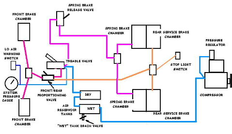
Schematic
Of The Clipper Air Brake System - Click To Enlarge |
Thus there are no "relay valves," or even
Spring Brakes, although the addition of the latter, being inexpensive
and easy to do, provides an extra margin of safey that is undeniable.
If your coach has not yet had this vital improvement added, it should be
done before you go anywhere. |
The basic elements of the system are these:
- 1. The Compressor - this is the heart of the system. Mounted on
the engine, it is driven from the engine's accessory drive - by a belt or
gears, and provides the compressed air necessary to operate the system.
The compressor is lubricated by pressurized oil fed by a line from the
engine's oil gallery, which drains back into the oilpan through a drain
line provided for this purpose.
- 2. The Pressure Regulator - this essential part of the system is mounted
on the compressor. It senses the system pressure, and engages or
disengages the compressor's function by temporarily disabling the valving. It
engages the compressor when the system pressure reaches a lower limit -
about 80 psi - and disengages it at the upper limit - about 120 psi.
The system reaching more than the upper limit could result in serious
damage to equipment and possibly personnel. When the compressor is
rendered "non-operational" by the regulator, it is still engaged and
turning; it just doesn't add to the system pressure until re-activated.
- 3. The Reservoir - this consists of a pair of air tanks - the
first in line designated the "wet" tank, the next the "dry" tank. The
"wet" tank provides, as well as air storage, a place for accumulation of
the condensation of
water produced by the compression and subsequent cooling of the air from
the compressor, as well as for the inevitable addition of some oil which
gets past the latter's piston rings. This tank must be drained of its
accumulated water/oil every day of operation. There is a drain valve
provided on the bottom of the tank for this purpose. Your dual-tank
reservoir system is located under the coach just ahead of the left rear
wheel. Condensation water tends to develop especially in cold
conditions - and it can make for real problems in freezing conditions!
- 3. (b) The "Blow-Off" Valve - As well as too little pressure, a
danger exists from the development of Too Much pressure. Thus the
installation of this spring-loaded check valve, mounted on the wet tank,
designed to release excess pressure in the case of the regulator not
cutting out when the maximum safe system pressure is reached - about 130
psi. In the case of a stuck (or frozen) regulator, severe system damage
could otherwise result. In your monitoring of your dashboard gauge, you
should also ensure that the pressure doesn't build up over into
the red zone. If the regulator is not cutting out, "fanning" the brake
pedal until you can safely stop and check your regulator is a great
idea!
- 4. The Lines - there is a system of lines and pipes connecting
the various components together. In the Clippers, this was done with
soft (bendable, or semi-rigid) copper tubing, although the modern
applications use special air-brake spec plastic tubing and connectors.
- 5. The Treadle Valve - the "brake pedal" operates this valve,
which directs air from the "dry" reservoir tank to the brake chambers,
located at the wheels. This valve is also a pressure regulator -
the greater the pedal movement, the more pressure is directed to the
brake chambers, and consequently the greater the braking power. This
results in a different "feel" to the brake pedal - with conventional
hydraulic brakes, there is a "feedback" provided by pressure felt with
the foot, although there is little relation between pedal movement and
application pressure. With Air Brakes, however, there is little
difference in feedback pressure - the degree of movement, or "how
straight is your ankle?" is the only indication of just how much braking
power is being applied
- 6. The Front/Rear Differential Valve - This is a distribution valve,
which regulates the relativity of the pressure being directed to the
front and rear brakes. In slippery conditions, you want less braking on
the front steering wheels than on the rears, since as the fronts approach
"lock-up," the steering goes away. For these conditions, the pressure
differential may be adjusted from the driving position - it will be
found located on the floor just ahead and to the right of the driver's
seat. (Below your right thigh.) Moving the
lever toward the rear takes some of the pressure off the
front brakes. In normal conditions (good traction), this lever
should be toward the front, removing the slippery-conditions
pressure bias.
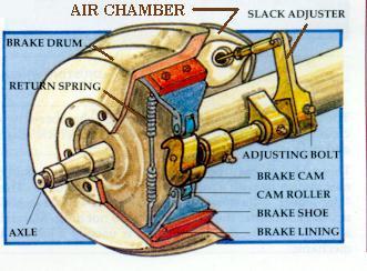
- 7. The Brake Chambers
- These are enclosed chambers which contain a
rubber diaphragm backed by a steel disc connected to the push rod
which actuates the brake in each wheel. Depressing the treadle valve
directs air into these chambers, applying the brakes - providing of
course that there is no excessive slack in the linkage. See below.
- 8. The Slack Adjusters - this is the name given to the levers which
impart rotary movement through the cam shafts to the actuator cams
inside the brake
drums, which force the brake shoes outwards against the drums.
These levers have a second function, that of providing a means of
adjusting out the slack which develops on an hourly basis as the
brakes are used.
|
|
Slack Adjustment is accomplished by means of a worm-and-pinion setup
between the lever and the camshaft - there is a bolthead provided for
adjusting the worm gear around the pinion. In high-use conditions, such as
mountain driving, they should be checked and adjusted on an hourly basis
- that's the reason for the brake-check areas found on most mountain
highways. On the other hand, flatland driving, where the brakes are
seldom used, will require less frequent adjustment. However, when in
doubt.......
- 9. The Push Rods - these serve to impart movement from the brake
chamber diaphragm to the slack adjusters. The pushrods too are
adjustable - in length. This is because, during the life of the brake
shoes, the angle of the pushrod to the slack adjuster (lever) at the
point of brake contact will change as the shoes wear. The ideal angle
of pushrod to lever is 90 degrees at this point - for the greatest
possible mechanical advantage. As the shoes wear, this angle must be
checked periodically, and adjusted as required. This is not a daily
procedure, however, and should never be confused with slack
adjustment!
- 10. Spring Brakes - There is no mechanical linkage from the driver's
position to the rear brakes. The Clippers were originally provided with
a "drive-shaft" brake, controlled by a lever and mechanical linkage
which imparts braking energy to the drive shaft. This system is not
nearly as powerful as the air-operated rear brakes; indeed it is
doubtful that it would suffice to stop the coach in the event of air
failure at speed on a good hill - and it would of course be of no value
in the event of a driveshaft failure. Enter the "Spring Brakes." These
provide parking and emergency brakes by means of exerting spring pressure
to the rear brakes, through the pushrods and slack adjuster systems
described above. They incorporate an extra "spring chamber" which is
"piggy-backed" to the regular rear brake chambers, but which contains a
very powerful spring which applies the brakes at all times, unless
defeated by a counter-operating air chamber which works against the
spring to disengage it from the system. Thus the brakes are applied at
all times, except when the spring brake chamber is pressurized. This
pressure is applied through a valve accessible from the driving position
- usually mounted on the dashboard. Until you have air pressure, the
vehicle cannot be moved - a good idea from a safety standpoint. In the
event of air pressure failure during operation, the brakes will be
applied by the springs, giving an "automatic emergency brake" aspect to
the operation.
The spring brakes may be mechanically defeated by being "caged"
mechanically - the chambers come supplied with special bolts which can
be inserted into the front of the chamber and engaged with the
diaphragm. There are nuts supplied with them as well, which may then be
tightened down, pulling the bolt and diaphragm, forward, and thus
disegaging the spring brakes. This is heavy work, and is best done when
the brakes are already caged by air pressure, ie disengaged at the dash,
but in the event of catastrophic air failure stopping the vehicle in an
embarassing place, they may be mechanically caged so that it may be
moved. in such event, be sure to block the wheels, and engage the
mechanical driveshaft brake before de-activating the spring brakes!
An additional caveat with spring brakes: NEVER attempt to dismantle
a spring brake chamber without the proper jigs and tools! There is
immense spring pressure which WILL cause you extreme damage if this
advice is not heeded! Spring Brake Chamber service is for experts only!
- 11. The Pressure Monitoring System - it will be seen by this
point that it is vital for the operator to know at all times what the
pressure of the system is. (See "know your pressure" below.) The
pressure monitoring components are:
- A. The Dash-Mounted Pressure Gauge - this provides visual indication
of the pressure of the system, and should be monitored at all times.
Thus, if for example, there is a system malfunction and the pressure is
dropping, your first indication will not be the locking up of the rear
wheels as the spring brakes apply. Exceptionally slow recovery of
pressure after brake application can give early warning of compresssor
problems, leaks, slipping drive belt, etc., so that the driver can pull
over and investigate before the situation exacerbates. If the regulator
sticks - and this can happen, especially in freezing weather - the
excessive pressure buildup will be indicated to the driver, who will
pull over and shut down so that the situation can be corrected before
disaster strikes.
- B. The Warning Light - In cases of driver inattention to the above,
the warning light, and it's companion listed next will serve to give
"last call" notice.
- C. The Warning Buzzer - this is the Very Last Call before disaster
strikes. During operation, things should never be allowed to get this
bad! - the pressure gauge should be as much a part of your "regular
checks" as oil pressure, temperature, speed, mirrors, and of course
what's happening out there in front.
- 13. The Air-Operated Switches
- The Stoplight Switch - located on the underside of the floor, just
ahead of the rear axle, this switch is plumbed into the distribution tee
which feeds the rear service brakes. When pressure is applied to the
system, the switch closes, providing power to the stop lights. Some
models have a "Stop" indicator lamp on the dash which signifies that
this switch has done its job. Some models use this switch directly to
operate the stoplights, others use it to energize a relay - mounted on
the switch itself - which provides a higher-current capability to the
stoplight circuit. See Wiring Schematic for connection details.
- The Low-Air Switch - This normally-closed switch is opened when
the Air Pressure reaches the 60 psi range - that at which the brake
system may be depended upon to operate. It is connected to the Low Air
Light and the Low Air buzzer. A spring-loaded Defeat Switch is usually
wired into the circuit, which may be held down at startup until the
pressure builds up, to silence the buzzer. If you have to hold the
switch down for more than 90 seconds, your system has problems and
should be investigated.
- Stoplight Indicator Switch - Some models had a second stoplight
switch mounted at the front, which closed when the system was pressured
up to operate the "stoplight" indicator on the dash. Or to tell the
driver that he had the brake pedal down. The use of such an indicator
light is not clear to your writer - this is no positive indication that
your stoplights are actually operating. One speculation is that, in the
early days of the Clippers, the exceptional power of the air brakes
required that the driver be aware of the possibility of surprising
following vehicles, and the dash "Stop" light was a way of reminding
him. Or her.
All of the above components of your Air Brake System should be checked
regularly, and maintained in tip-top condition.
Hit your browser's "back" button to return to the index
