Would you like to make this site your homepage? It's fast and easy...
Yes, Please make this my home page!
The Flxible Clipper Handbook
- by Pete Snidal (C)2004
Relays 101
What A Relay Is, and Why You Need It
A Relay is a sneaky way of switching short and/or heavy lines
carrying high current with thin, possibly long lines and skinny
switches carrying very low current.
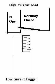 |
A low-current electromagnet is used to draw down a
spring-loaded bar to complete the high-current circuit. This
allows low-current switches and long, thin wires to control
high-current devices, such as motors, light systems, etc. through
shorter and heavier-wire paths.
To wire it in, you need only identify the low-current
terminals - they will make the relay "click" when connected to
power - and the high-current terminals - they will close when
the "click" is heard from the low-current connection. A diagram is
usually supplied with the relay.
It allows you to run a really heavy (#12, say) wire from your
battery via a short path and then to "trigger" this line with a
low-current much less direct line from the "office."
|
Do You Need Any?
One of the features of our beloved Flx's is their length - the
alternator, voltage regulator and batteries are in the back of the bus,
and the light switches and front lights are 35 feet up in the front.
The current path is even longer for the rear lights and other load
devices at the rear - from the batteries up to the front panel, through
the switch, and then all the way back again to the light(s), starter
solenoid, demister motor, or whatever. This 70 feet of wire can eat up a
fair amount of power, especially at higher amperages. The taillights/rear
marker light circuit, for example. This is especially important since
today, the expectation of following drivers is higher than it
once was for lights on the rear, and for this reason, many flx owners
have added to the complement of lights showing at the rear. In many
cases, we may be going slower than much of the rest of the traffic,
and this is an additional reason for some extra lights. And of course,
extra lights just compound the problem of the voltage drop in the 70-ft
circuit. Adding a relay can reduce the length to a matter of the width
of the bus, rather than the length.
A second feature of our busses is their age - the wires in there aren't
getting any younger, nor are the connections and joints along the way.
But this current path is almost certainly adequate for the low draw
required to energize a relay. Thus, for example, the 10 Amps or more
required for the rear tail and marker lights can be carried by a short,
fat current path directly from battery through relay to lights, and the
much lower current required to energize the lights will easily be
carried by the existing light circuit - ending now at the relay, instead
of at the individual lights. Similarly, a relay may be used in case of
difficulties with the starter solenoid - itself another, larger relay -
or accessories such as a radiator mister pump.
Testing: Will A Relay Help?
A relay is only necessary in cases in which the standard wiring is overtaxed.
To test whether this applies to your application, it is useful to do a
Voltage Drop Test.
In this test, you look for a small voltage where there shouldn't be one -
between the battery "hot" terminal (the one not grounded to the chassis)
and the load device feed wire, as close to the device as possible.
When the switch is open, there should be full battery voltage between
the battery and the device, - ie across the switch - and when the switch
is closed, this voltage should fall to 0. If any voltage is indicated,
this "drop" signifies that power is being wasted in the circuit from
battery to load.
For example, let's check for voltage drop on our example, the rear
lights. First, locate the terminal on the rear board which feeds them.
This should be terminal 17 - you can check simply by finding the
terminal which is "hot" when the marker/tail lamps are on, and isn't
when they're off.
Let's look at the current path for this circuit. The power must travel
from the batteries to (most likely) the terminal on the starter solenoid -
to the hi-current (#6 Cable) terminal (probably 13) on the rear board,
up the cable to the busbar (behind the switch panel), through the
"Mark-Taillamp" switch, and back down to the rear terminal board 17,
before it is distributed to the tail and marker lights. That this
70-foot path may be showing some resistance, meaning lights dimmer than
necessary, should come as no surprise. To see just how bad the
situation is, just set your multimeter to Low DC Volts (0-5 is good),
and check the voltage between the "hot" starter solenoid terminal - or
the Big Amps rearboard terminal 13 - and the taillight terminal (13).
With the switch off, the voltage should read full battery voltage, since
there is so little current draw by the DC Voltmeter. But with the lights
on, there should be no voltage showing, ie no "voltage drop." If there
is (and I'd be surprised if there isn't!), this can be corrected by
"jumping" the two terminals together (which would result, of course, in
the voltmeter reading dropping to 0). If this results in considerable
brightening of your lights, you know that fitting a relay will be a big
help!
(The purists among us might insist that, in an ideal world, there should
be NO voltage drop in the 70-ft circuit, and that A Real Man would just
correct the problems - by cleaning/replacing all terminal connectors,
switches, and possibly conductor wires. Possibly true, but it's also
possible that you still wouldn't completely eliminate the drop,
and in any event, the relay solution is much simpler.
Doing The Job
First, ensure that you have the necessary parts:
Tools and Materials
- A Relay - Your local auto supply store will have a selection
of small horn relays. Bosch make a nice one.
- Wire. Pick up a roll of #14 stranded automotive wire. Get it
in red for (-) ground systems, black for (+) ground.
- Crimp connectors - some spades, for the relay, and a ring or
two, for the battery.
- Crimping tool for the connectors
- The usual tools - screwdriver, pliers, wire strippers
Once the materials are on hand, it's just a matter of following these
steps:
IMPORTANT! - First disconnect your battery from the system to
avoid unpleasant surprises such as fire, etc when working with the
connections.
- 1. Referring to the diagram etched on the relay case, determine
which terminals do what. Two terminals will be the low-current'
"energizer" terminals, and two the high-current "load" ones. The
drawing at the top of this page may help. If there's no diagram, you can
use this strategy.
- 2. This would be a good time to attach spade terminals to a pair
of wires for the high-current circuit. Cut two pieces of fresh #14
wire long enough to reach between the intended mounting point and the
terminal board.
- 3. Strip each end of each piece, and attach a female spade
to one end, and a ring terminal to the other end of one of them. Attach
the other one to the fuse holder, and leave the other end of the fuse
holder alone for the time being.
- 4. Now for the energizer circuit. Using a different colour wire,
#16 is fine - prepare two more pieces by stripping their ends, and
attach female spade terminals to one end, ring terminals to the other.
- 5. Referring to the diagram on the relay case, clip the wires to
the appropriate terminals
- 6. Mount the relay close to the rear terminal board. Ground one
of the energizer terminals by fastening its ring connector under the
head of the screw which mounts the relay to the body sheet metal.
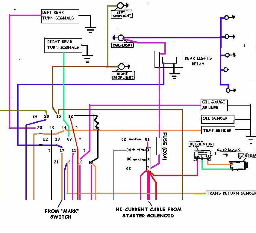
The Rear Circuit Board, Showing Rear Light Relay - Click to Enlarge
|
- 7. Disconnect the taillight feed wire from the board. This should
be terminal 17 - it's the one that goes "hot" with the rear lights on.
- 8. Using a butt connector (or, better still, shrink tube and
solder) connect one of the relay's hi-current wires to the taillight
wire - the one that came off of terminal 17.
If length permits, just strip the taillight wire, crimp on a spade
terminal, and attach it directly to the relay's other hi-output
terminal.
- 9. Connect the other low-current energizer terminal wire to the
rear board terminal which previously fed the taillights. (probably 17).
This will provide current to energize the relay from the MARK switch in
the cockpit.
|
- 10. Finally, connect the remaining relay hi-current terminal wire
- the input - through a fuse to the rearboard terminal 13 - the one with
the fat wire coming from the starter solenoid. (Hi-current feed.)
- 12. Re-connect the batteries and test your rear lights. In the
event of non-performance, check using the list below
Trouble-Shooting List
If, after all this, you find you no longer have rear lights, it's time
to do a systematic check of connections. Here are some suggestions:
- 1. Power input to relay: Check at the input line fuse for power
to ground.
- 2. Power output from relay to lights: use a temporary jumper to
jump across the relay terminals from in to out. If this lights the
lights, you know that the relay is faulty, or that it is not closing
with power from the light switch.
- 3. Relay function. First, jump from a hot line
(such as the new fuse input) to the relay trigger line - terminal 17
on the rear board as shown in the diagram. This should produce an
audible click as the relay closes. If you hear the click, have someone
check for taillights.
- 4. Power from light switch to relay trigger terminal. Check for
power at relay trigger terminal with light switch on.
- 5. Relay trigger ground connection. If all above works, jump
from a good ground to the trigger ground relay terminal.
Other Uses For Relays
In the same way, relays may be used for other purposes at the far
reaches of your bus. For example, if you're using a radiator mister
system, with a rear-mounted pump, you can wire yet another relay in
the same fashion as described above. Thus, you'll require less current
capacity for your trigger line.
Another use for a relay is to eliminate high-resistance problems in the
starter trigger circuit - if you sometimes have to go back there and
trigger the solenoid by hand, you can wire a relay to fire the solenoid
- a relay for a relay, so to speak.
No Connection Diagram?
There is often a little teensy diagram on the relay itself, but your
mileage may vary. If you have no diagram, you can still use the
following coping strategy to determine connections:
There will be 5 connections: Two for the energizer circuit, and
three for the main circuit - one common, or "input", and two "output," -
one "normally closed," and one "normally open." We will use the
"normally open" pair, meaning that it closes when the relay is energized
by power from the light switch.
- First, find the energizer circuit. Which two?
We will use a "hot" wire from the battery, and a ground wire.
Clip a jumper to each battery terminal. Attach the ground
clip to any tab on the relay.
- Try a hot wire to each of the others in turn, looking for a "click."
- If you don't get a "click," move the ground clip to the
next one. Repeat step 2. Keep doing this until you identify
a pair which will make the click. (Close the relay) Polarity
doesn't matter; either of these two may be grounded or made "hot"
to energize the relay. Mark them.
- You now have 3 terminals left. One of these is a
"feed," or input terminal, and the other two are "load," or outputs.
We will only have to identify two of these remaining terminals - those
which are connected when the relay is energized.
-
First, energize the relay by connecting the battery to the energizer
terminals. then, using your multimeter on "ohms," find the two that
are connected when the relay is energized. These are your new "high
beam switch," or "Load" terminals. Mark them. Disconnect the energizer
power, and check to make sure that they are now open.
How To Connect It
Hit your browser's back button to return to previous page
