|
|
|
The only difficulty with this scheme is actuation - how can the air-operated rear brakes be applied in the event of loss of air pressure (emergency) or for parking, when the air supply eventually depletes due to the air compressor being shut down with the engine (parking)?
Enter the Spring Brake. These utilize a second system of brake actuation - only for the rear brakes - being applied by very strong springs, which duplicate the action of the otherwise air-operated brake chambers, by the addition of "Spring Chambers," which are "piggy-backed" onto the former. This system, although not originally supplied on the Flx Clippers, is a far superior and much safer one, and thankfully may fairly easily be retrofitted to the Clippers. The job is in fact only a few hours' work, and requires less than $200.00 worth of parts and pieces. And, best of all, you can leave your original driveshaft brake in place for extra backup!
 |
|
If your chambers are still single, you should have a knowledgeable shop or mechanic install spring brakes on your rig. If you're not already confident in your competence to do this job, do not consider this article a "how-to." Rather, it is intended to acquaint you with what is involved with the job.
First, let's look at Spring Brakes in detail. Following is an excerpt
from an earlier article on Air Brakes in general:
(Danger Note! -
Spring brake chambers, obviously, have big, heavy springs in them.
Attempting to dismantle them without proper information and precautions
will earn you a Darwin Award!
This kind of parking brake has a major difference over the brakes we'
re all used to - if the system loses its pressure, the de-application
pressure is also lost, and the parking brakes will come on as the
pressure decreases - providing an "automatic" setting of the parking
brakes if system pressure is lost on the road. This is another reason
we must pay attention to system pressure - if it drops to the danger
level, you need to pull over in the first safe place, while you still
have enough air to maintain control over your brakes, or you just may
find yourself stopped in the middle of the freeway!
And don't ever forget, the rear brake slack must be done with
the brake springs caged! - So you'll have to chock your wheels and
set your brake control to the "off" position.
First, the Caveats. A little discussion of what could go wrong:
Assuming that didn't happen (thank gods), you're still stuck with your
emergency lights flashing, in the middle of the lane. You've got to get
your coach out of the way as soon as possible, meanwhile first setting
out flares and directing traffic around this obstruction you've created.
(With luck, you've got some crew aboard to help with some of this.)
Your brakes can be released, fortunately, by using your "caging bolts" to
withdraw
the brake springs. It means getting out and under, and some sweaty work
with a big wrench for 10 or 15 minutes. Hopefully, you've set blocks
under your wheels, and set your old parking brake (if it's still there),
so your bus doesn't roll over you when you get the brakes off, and you
can then close your parking brake valve - to eliminate any more air loss
- and drive to somewhere where you can diagnose and repair the problem
sans your parking/emergency spring brake. (Which is hopefully backed up
by your still-there driveshaft brake. Belt and suspenders.)
Either of these scenarios assumes the main possible problem with your
installation - that of air loss from your new line letting go. So we see
right away that this new airline - from take-off point through control
valve to brake chambers - as with all brake components - MUST be reliable
and totally secure!
Other possible problems could develop from faulty installation of the
new brake chambers themselves - failure to tighten the mounting bolts
properly, install safety cotter pins in the linkage clevises, or
possibly failure to adjust the rear brakes properly after installation -
remember, your rear brake adjustment must now be done with the brake
springs caged by air pressure or bolt installation!
However, whether you decide to do the job yourself, or "farm it out,"
here are the steps involved:
Tubing may be of soft (semi-rigid) copper, or plastic. For air work of
any kind, always ensure that you are using the proper schedule (a rating
of pressure and quality) for the job at hand. Different grade tubing is
used for aquariums and Pepsi-Cola dispensers than for Air Brakes!
There is a special type of compression fitting for hi-grade plastic
tubing, approved for airbrake use, which uses a special insert which
is slipped inside the tube before the nut is screwed to the fitting.
This reinforces the end of the plastic tube sufficiently for a solid
compression joint to be made.
Often, the compression bushing forces its way into the tubing, so
although the joint may be connected and reconnected repeatedly, bushings
should not be reused for other connections. New bushings should be used
each time, and the tubing recut to a fresh surface.
The next step is to remove the first of your existing brake chambers.
Before you do this, check that the existing pushrod length is correct.
To do this, use a Brake Buddy(TM) or other suitable tool to move the
slack adjuster to full brake position. Check the angle between the
pushrod and the slack adjuster lever at this point. If the angle has
gone to less than 90 degrees (this is a natural occurence due to brake
shoe wear), you'll want to lengthen the pushrod by adjusting the
position of the clevis - ie, make your new pushrod just a bit longer.
Remember this for when you set the length of your new pushrod. Then,
locate the clevis pin at the outer end of the slack adjuster. Remove the
cotter key from the end of the pin, and then remove the pin. Now you're ready
to detach the air line between the chamber and the distribution tee -
look for the swivel fitting and unscrew this first. (One end will likely
be a "swivel" fitting, and the other will be a pipe fitting that
requires twisting the whole line to move.) Then you can unscrew
the two big nuts that hold the brake pot onto the bracket welded to the
rear axle, - these are fun; one of those 1/8 turn at a time
propositions. Once you get them off, you'll be able to lift the pot free
of the axle. Now for some bench work.
Once you've got the first brake chamber on the bench, you can use it to
determine where to cut the pushrod supplied with the first of your new
double-pot chambers. - They come in a universal length, to be cut for
the particular application of the new owner.
First, measure the distance from the mounting face of your old pot to
the center of the clevis pin holes. Make a note of this distance - the
target is to cut the pushrod on the new double pot, and to reinstall the
clevis so the distance is the same.
Now, examine one of your new double pots. There is an air chamber at the
rear, just as with your old one, but there is an additional air chamber
"piggy-backed" to this one. The latter chamber contains a very strong
and highly compressed spring - DO NOT EVER under any circumstances
contemplate removing the retaining ring which holds this spring chamber
together. This WOULD result in heavy damage to your person! - that
spring is under STRONG tension! Disassembling Spring Brake Chambers
without the proper tools, fits in with taking hammers to old TV tubes as
a qualifier for the Darwin Award.
And soon it will be under even more tension, since the spring brake must
be de-activated before we continue with the installation. This will
mean using the cage bolt to hold the spring tensioned, once we get it
that way. There are two ways of tensioning the spring. The first is
just to fit the cage bolt into the end of the chamber - it will rotate
and lock into place inside the spring retainer - and use a suitable
wrench to tighten the bolt, drawing the spring up against the end of the
chamber. This starts out to be a fairly easy chore, but as the spring
tension increases, the torque required increases substantially - the nut
will actually get quite hot, as will you yourself. It can be quite a
workout.
Or you can use shop air pressure, if you have it available, to do the
work for you - this is easier on the nut and threads, and much easier on
your arm. Chuck the air chamber securely in your bench vise, and remove
the protective plug in the spring air chamber air fitting. Then fit your
blow gun into the air fitting, and apply air pressure. This will force
the spring up against the end of the chamber, releasing tension on the
bolt. This will allow you to run the nut down the threads with much
less effort - you'll need 30-40 psi to pull the spring completely back.
DO NOT get your fingers between the nut and washer, or washer and
chamber - if the blow gun slips out of the fitting, spring pressure will
suddenly return with a vengeance!
Once you have the spring completely caged, the service brake chamber
will operate just as did your old one, and you may continue with the
installation. First, returning to the original air chamber, loosen off
the locknut and unscrew the clevis. Now, you'll want to cut the new
pushrod so that you can screw on the old locknut and clevis to attain the
same effective length (mounting flange to clevis length) as your old one.
(This is the time to adjust the length for that 90 degree angle if
necessary!)
Do the measurements and then make the cut - with hacksaw or Skilsaw and
cutoff disk - and screw on the locknut and the clevis - you may have to
dress the end of the pushrod with a fine file, depending on how violent
the cutting process was. Be sure to tighten the locknut securely
against the clevis.
This done, you'll be able to mount your new dual brakepot in place
of your old one. Remove the new mounting nuts, and introduce the new
chamber to the flange on your rear axle. Re-fit the clevis pin while you
can still move the chamber around on the flange, and then fit the
lockwashers and mounting nuts. Snug them up, and then, using your brake
buddy or similar tool, pull the slack adjuster against the brakes, and
check that the angle between pushrod and slack adjuster at this point of
application is a bit more than 90 degrees. If it is less than 90, you'll
have to adjust the pushrod length by means of the clevis until it is
less than 90 - as the brakes wear, this angle will increase past the
ideal 90 degrees until it is more, and you'll have to adjust it
again. Thankfully, this is not a daily chore, like adjusting the slack
adjuster. Once you've got the angle right, (no pun intended) be sure to
secure the clevis pin with a new cotter key. Ensure that the pot
mounting nuts are now tightened securely.
Now, adjust the slack adjuster for 1/4" or a bit less of free play - meaning
so that you can move the end of the adjuster only this much before the
movement is stopped by the shoes butting against the inside of the brake drum.
This adjustment is done by rotating the 9/16" bolt head which rotates
the worm in the slack adjuster lever. Tighten the bolt until you can get
no movement, then back it off until you can move the pushrod about 1/4".
You may now re-fit the service brake air line to your new service brake
chamber. You will likely need a new fitting or two - a 45 degree
will likely be required to re-orient the line for the new fitting
position on the air chamber. Use high-quality brass fittings, obtainable
at the truck supply house where you got the air chambers and air lines.
Resist any temptation to use anything but the highest-quality fittings
suitable for airbrake use. If in doubt, ask the parts man! Be sure to
route all brake hoses so that they won't be able to snag on any objects
projecting from the roadway.
This done, repeat for the other side. Once the brakes are re-connected,
you have as much brakes as you did before, with a pair of new,
still-caged spring pots which give you the potential to continue with
spring brake installation. All that's left to do is to provide for a
driver-controlled air supply to the spring brake chambers, and to air
them up and remove the caging bolts.
Now, to provide air supply to the tee. First, decide on your routing
for the air line from tee to the valve position at the driving position.
DO NOT even contemplete running the line below any cross-members - if
this line catches on any obstructions and tears out, your rear wheels
will lock up immediately! You'll likely have to drill a hole in each
cross-member for your new line. Obtain the proper fittings to adapt
from the thread type of your tee to the fitting type of your chosen line
- you can use soft copper of the proper schedule (thickness and psi
rating) as was used on your original air system, but you'll likely chose
the modern air-brake approved plastic line and matching
ferrule-and-filler end fittings. You'll likely need adapter fittings
from this type of fitting to the threads of your tee, and to those of
your control valve at the driver end. (See earlier discussion of types
of threads and fittings.) I used 3/8" line; this is a minumum size; you
may chose to use 1/2". (Remember a high-capacity, reliable air supply is
essential to safe operation of your coach with spring brakes.)
When you purchase your line, be sure also to buy rubber grommets to
mount where the line goes through the cross-members, or any other metal
parts of the coach. This is to inhibit chafing of the plastic, another
possible cause of catastrophic unwanted brake application. The grommets
will tell you what size to drill your holes.
Once the holes are drilled, route the line from the tee to the driving
position - you'll likely want to mount your control valve on the
dashboard.
This last one can be perplexing. The original Flxible air system, using
semi-rigid copper tubing, presents a number of problems to break into a
place such as the supply to the treadle valve, or even the air horn
button on the floor. After some investigation, your writer chose the
supply to the air pressure gauge. This is not a high-volume connection,
since the air gauge supply is only 1/4" line. However, my reasoning is
that connecting into the air gauge supply close to the gauge means that
any leakage from the new tee downstream to the springbrake pots will
show in the gauge quickly, and I'll just have to monitor and be ready
for it. So I put a tee in the back of the pressure gauge, and connected
the existing line to one side, and the input to my springbrake valve on
the other. The line from the springbrake valve to the distribution tee
at the rear axle is 3/8".
Once everything was connected, I started the engine, and when pressure
was up to snuff, opened the springbrake control valve. This pressurized
the springbrake chambers, taking the pressure off the caging bolts,
which I was then able to remove as finger-tight. Releasing the valve, of
course, sets the brakes.
This type of installation would require the addition and mounting of the
separate air tank and relay valve, and tapping into the system in the
region of the reservoir feed - or just after the dry tank. This means
complications dealing with the semi-rigid copper supply lines, and I
preferred to leave well enough alone.
Spring Brakes - Parking Brakes for Air-Equipped Vehicles
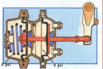
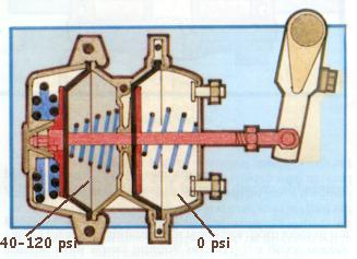
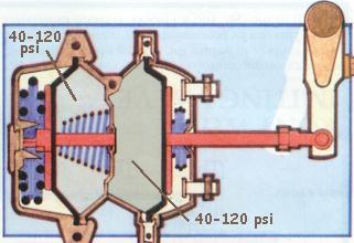
Since it would be ridiculous to expect an air
chamber to maintain pressure over long periods of parking, the
spring brake has just that - a spring applies the rear brakes,
which are therefore always on, unless the spring is "caged" by a
second additional air chamber, "piggy-backed" onto the one already
there for the regular service brakes. To de-apply the parking brakes,
the system must first be brought up to pressure (the compressor) and
then the spring chambers are charged with air by means of the
dash-mounted parking brake valve. This offsets the springs and
lets the vehicle move. (In most cases, there is also a mechanical
means to cage the springs in case of emergencies - you get out and
under, remove the dust cap, and screw the cage bolts up by hand.)
Important Safety Note!
Does this mean that you will always have an automatic emergency
brake, which will come on every time you lose pressure? No, there is
still one eventuality which will not - ever - be accounted for, and that
is excessive adjuster slack! The final determinant in the
airbrake equation is always the mechanical linkage between the
air chamber/brake pot and the actuation lever - the slack adjuster. If
any adjuster - or all of them - is too slack, no amount of spring or air
pressure is going to put that brake on - the push rod will move to its
full extent, and 20,000 Lbs of coach will sail blithely on into whatever
disaster awaits. NEVER let your adjusters get too slack! Check them
daily, and more than that when you're using your brakes more than usual.
Expertise
Since this is a vital part of the safety considerations for operating
your coach, a certain level of mechanical expertise is required, and
certain standards must be maintained during this installation. If in
doubt, enlist the services of a certified mechanic, or take your Clipper
to a reputable shop to have the installation done. Still, it may be a
help to read on, if for no other reason, just to understand what will be
involved in the procedure.
1. Sudden release of spring brake pressure
Imagine driving along on the highway, traffic behind you fairly heavy,
and perhaps following a little too close, when suddenly, without
warning, _your_rear_brakes_lock_up! The possiblities for bad craziness
are manifold. First, you may be involved in being the star player in a
rear-end collision - or even a multi-car pileup! You can imagine the
repurcussions when the insurers discover that your homemade band-aid and
clothespins spring brake conversion let go!
2. Development Of A Sudden Air Leak
With this one, your low air light and buzzer suddenly come on - or,
better yet, you noticed your pressure gauge dropping very fast and
without warning, or maybe (unlikely) you even heard some air hissing and
then looked at the gauge. This may have been the result of your
retrofitted spring brake system leaking air somewhere between the
take-off point (from your existing system) and the brake chambers,
or it could be from some other cause. In any event,
you're losing air pressure, and this means you have to get that puppy
over to the side of the road before the brake springs take over due to
lack of sufficient air pressure in the de-application chambers. About
40 psi is where it starts to happen. This scenario is not nearly as
scary as the first, depending of course on how rapidly the air is
escaping, and how soon you became aware of the problem, but it can still
give cause for wishing your new plumbing had been made a lot more
secure.
Doing The Retrofit
First, you'll need to assemble the necessary parts and pieces. Main
ones are:
A Word On Pipe And Line Fittings
There are a number of types and standards of what most people just refer
to as "pipe fittings." They vary in how they seal, thread pitch and
diameter, and purpose. The different main types are not
interchangeable, and MUST not be confused with one another. To go from
one type to another requires adapter fittings in between. (eg, pipe
thread to tubing flare.) The basic types you will encounter are:
To reiterate, adapter fittings must be used to connect joining
methods of different kinds together. Thus a NPT (National Pipe Thread)
Tee may be connected to plastic or soft copper tubing, providing a
fitting is used which is NPT on the tee end, and Compression or Flare
on the other (depending on what you decide to use on the tubing.)
Doing The Retrofit
1. The New Brake Chambers
First, secure your new brake chambers. You'll want series 30 dual
spring and service brake chambers. The "30" is the size - refers to the
area of the diaphragm. Fortunately, the bolt patterns for mounting are
standard. The push rod length varies, but your new universal-fit
chambes will have pushrods that are too long, and threaded for their
entire length, so you'll be able to cut them down to fit. They may be
ordered at any truck parts outlet. If in doubt, take one of your old
ones in so the counterman can get any dimensions he may need.
2. The Air Supply
A. The Distribution Tee And Air Lines
Now, you'll want to mount your new air supply tee on the cross member
just ahead of the rear axle. Mount the tee beside the existing one for
supply air. Fit the pipe thread-air hose flare adapters, angle fittings,
and your new flexible air hoses as required, connecting the air chamber
fittings to the tee. This tee may be a standard 1/2" pipe tee, with a
mounting bracket brazed to it, or your parts supplier may be able to
come up with something more exotic. Just get a size that will allow
direct fitting of your brake hoses. You'll likely need an adapter for
the air line from up front.
B. The Control Valve
There are a number of possiblities for control valves. See your local
supplier for options, and choose the kind of valve you want - of course,
you'll be using one designed specifically for the purpose. The
other consideration is where to mount it - generally on the dash, and
from where you'll be drawing the air supply to feed it.
Possible Problems With This Installation
The Anal-Retentive among us, of course, will have issues with this
installation, feeling that the possibility of unwanted sudden air loss is not
sufficiently provided for, due to the size of the feed. So let's start
our considerations with the full belt-and-suspenders possibility: the
separate springbrake air tank.
Separate Tank
To be more sure of lots of air supply - to cover the eventuality of a
diaphragm or fitting leak, for example, some installations use a
separate springbrake air reservoir, fed by the regular system through a
one-way (check) valve. This tank is located as close as practical to
the springbrake pots, and connected with large-diameter tubing - ie, 1/2"
- the same size as the flex hoses - fed by a relay valve - a
special valve which connects the chambers and tank more directly, and
is itself controlled by a second circuit from the driving position.
Once the relay valve is opened, charging the springbrake chambers, the
springbrake feed becomes a closed system, and will be unaffected by even
total loss of airpressure in the main system. The brakes will be uncaged
only when the relay valve is opened.
Second Possibility: Larger Supply Capacity
The second possibility for improvement of my system would be a larger-capacity
feed line to the distribution tee. Once again, this would require opening up
the semi-rigid copper feed line to the treadle valve. It could be done,
introducing a compression tee in this line, but I chose not to disturb
the existing service brake system. I am concluding that, if no leaks
develop downstream of the tee into the air gauge line, there will be no
problem, and if a leak does develop, it will show as a serious drop in
pressure indicated by the gauge.
---------
But Not Always...
That is, provided the deapplication pressure is provided from the
reservoir of the regular system. In some cases, the de-application
pressure is provided from a second special reservoir, supplied from the
first one through a one-way check valve, so that pressure loss in the
main system will not affect the pressure in the spring brake reservoir.
In this case, the spring brakes will only be applied when the dash-
mounted valve is operated to exhaust the air from the spring brake
chambers. This eliminates the "automatic" aspect of spring brake
application in the case of loss of pressure in the service brake
system, but allows greater operator control in that the second
reservoir can allow the operator to de-apply the brakes for such
things as small movements once the spring brakes
have brought the vehicle to a stop.